|
|
|
|
O Interfata grafica "buna la orice"!
De data aceasta revin cu un soft experimentat, construit
dupa exemplele grafice din bibliotecile ESP32, si modelat in asa fel incat sa poata fi usor inteles si
modificat pentru nevoile oricui. Asa cum mi s-a sugerat, incerc sa nu reinventez “apa calda”
dar sper ca articolele mele sa vina in sprijinul celor mai putin priceputi sau
incepatorilor. “Experimentatii” pot interveni cu idei constructive. Aplicatia se vrea o interfata grafica ce poate fi folosita
pentru nevoile radioamatorilor care vor sa-si construiasca un S-metru sau o
tastatura deosebita, sa foloseasca comunicatia WiFi in aplicatii sau sa
controleze parametrii dispozitivelor construite in jurul placilor ESP32-S.
Recomand aceasta placa pentru performantele ei, pentru usurinta programarii cu
Arduino IDE si pentru faptul ca poate folosi o antenna exterioara conectata cu
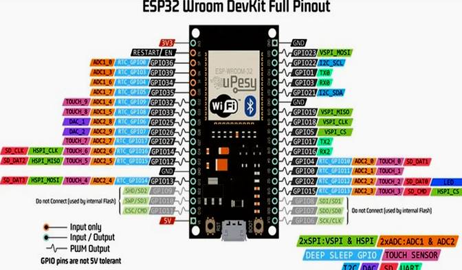
foarte mare usurinta. Articolul anterior are toate elementele Hardware de
conectare a unui ESP32 cu un Display ILI 9341 SPI. Nu mai revin la acest aspect intrucat scriptul care urmeaza
contine din nou conexiunile pinilor, in schimb voi posta o noua imagine cu Pin Out-ul
microcontrollerului in idea ca studiind-o cu atentie veti constata unele
restrictii in folosirea intarilor si iesirilor GPIO. Prezentarea Software: Softul prezentat in continuare va fi explicat pe larg cu
toate amanuntele in asa fel incat cu putin efort, va putea fi inteles ca logica
a functionarii. Am folosit si adaptat rutine din exemple publicate in
bibliotecile ESP32 existente la adresa: https://github.com/Bodmer/TFT_eSPI Keypad_240x320 si TFT_Meters sunt
sursele de baza pentru Interfata Software prezentata, si care dupa cum
am mai spus, poate fi usor modificata la nevoie. Comentariile sunt scrise in EN cu scopul de a face posibila
intelegerea de catre o categorie mai larga de cititori. Iata fisierul .txt care trebuie redenumit .ino pentru prelucrare in Arduino IDE: ///*******************************************************************/// ///******************* GOOD INTERFACE TO ANYTHING
********************/// ///*************** by DORU SANDU /
gocomraex@gmail.com****************/// ///************************************ ex.YO9CXY
********************/// ///*******************************************************************/// #include <WiFi.h> #include <SPI.h> #include <TFT_eSPI.h> // Hardware-specific
library /* // Pin configuration for the ILI9341 display/2.8inch &
ESP32 S Dev Board #define TFT_CS 5 // Pin-29 ESP32 "VSPISS"
(GPIO_05) #define TFT_DC 33 // PIN-8 ESP32 "ADC1_5"
(GPIO_33) //#define TFT_MISO 19 // MISO---> ESP32 pin 31
"VSPI_MISO" (GPIO_19) #define TFT_MOSI 23 // MOSI---> ESP32 pin 37
"VSPI_MOSI" (GPIO_23) #define TFT_SCK 18 // SCLK---> ESP32 pin 30
"VSP_ISCK" (GPIO_18) #define TFT_RST 32 // PIN-7 ESP32 "ADC1_4"
(GPIO_32) #define TOUCH_CS 27 // PIN-11 ESP32 "ADC2_7"
(GPIO_27) */ TFT_eSPI tft = TFT_eSPI(); // Invoke custom library /* #define ILI9341_BLACK 0x0000 #define ILI9341_NAVY 0x000F #define ILI9341_DARKGREEN 0x03E0 #define ILI9341_DARKCYAN 0x03EF #define ILI9341_MAROON 0x7800 #define ILI9341_PURPLE 0x780F #define ILI9341_OLIVE 0x7BE0 #define ILI9341_LIGHTGREY 0xC618 #define ILI9341_DARKGREY 0x7BEF #define ILI9341_BLUE 0x001F #define ILI9341_GREEN 0x07E0 #define ILI9341_CYAN 0x07FF #define ILI9341_RED 0xF800 #define ILI9341_MAGENTA 0xF81F #define ILI9341_YELLOW 0xFFE0 #define ILI9341_WHITE 0xFFFF #define ILI9341_ORANGE 0xFD20 #define ILI9341_GREENYELLOW 0xAFE5 #define ILI9341_PINK 0xF81F */ #define TFT_GREY 0x5AEB #define TEST_LED 15 // LED const char* wifi_ssid = "Denumirea retelei locale WiFi"; const char* wifi_psw = "Parola retelei locale WiFi"; int16_t previousRSSI = 0; //******************************// // Keypad start position, key sizes and spacing #define KEY_X 75 // Center of key W #define KEY_Y 230 // Center of key Y #define KEY_W 60 // Width of Keys #define KEY_H 30 // Height of Keys #define KEY_SPACING_X 5 // X gap !!!Used for multiple
columns #define KEY_SPACING_Y 5 // Y gap !!!Used for multiple rows #define KEY_TEXTSIZE 1 // Font size multiplier //******************************// // Using two fonts since numbers are nice when bold #define LABEL1_FONT &FreeSansOblique12pt7b // Key
label font 1 #define LABEL2_FONT &FreeSansBold12pt7b // Key
label font 2 // Create 9 keys for the keypad - Number of Keys / Maxim
Number of Characters char keyLabel[9][5] = {"-sta", "spk+",
"sta+", " ", "stop", " ",
"-pwr", "spk-", "pwr+"}; uint16_t keyColor[9] = {TFT_RED, TFT_ORANGE,
TFT_DARKGREEN,TFT_BLACK, TFT_GREY, TFT_BLACK,TFT_BLUE, TFT_MAGENTA, TFT_NAVY}; // Invoke the TFT_eSPI button class and create all the
button objects TFT_eSPI_Button key[9]; WiFiServer server(80); //******************************// /* Available ESP32 RF power parameters: For 19.5dBm of output, highest. Supply current ~150mA WIFI_POWER_19_5dBm // 19.5dBm (80) WIFI_POWER_19dBm // 19dBm (78) WIFI_POWER_18_5dBm // 18.5dBm (72) WIFI_POWER_17dBm // 17dBm (66) WIFI_POWER_15dBm // 15dBm (60) WIFI_POWER_13dBm // 13dBm (52) WIFI_POWER_11dBm // 11dBm (44) WIFI_POWER_8_5dBm // 8dBm (34) WIFI_POWER_7dBm // 7dBm (28) WIFI_POWER_5dBm // 5dBm (20) WIFI_POWER_2dBm // 2dBm (8) WIFI_POWER_MINUS_1dBm // -1dBm (NEVER USE FOR
PROGRAMMING !!!) For -1dBm of output, lowest. Supply current ~120mA */ const int wifiPowerValues[] = { WIFI_POWER_2dBm, WIFI_POWER_5dBm, WIFI_POWER_7dBm, WIFI_POWER_8_5dBm, WIFI_POWER_11dBm, WIFI_POWER_13dBm, WIFI_POWER_15dBm, WIFI_POWER_17dBm, WIFI_POWER_18_5dBm, WIFI_POWER_19dBm, WIFI_POWER_19_5dBm }; const char* wifiPowerNames[] = { "WIFI_POWER_2dBm", "WIFI_POWER_5dBm", "WIFI_POWER_7dBm", "WIFI_POWER_8_5dBm", "WIFI_POWER_11dBm", "WIFI_POWER_13dBm", "WIFI_POWER_15dBm", "WIFI_POWER_17dBm", "WIFI_POWER_18_5dBm", "WIFI_POWER_19dBm", "WIFI_POWER_19_5dBm" }; int IndexPower = 10; // Initial value for wifiPowerTx (0 to
10) //int valueSearched
= wifiPowerValues[IndexPower]; // Display
Power in dBm //const char* ConstPower = wifiPowerNames[IndexPower]; //
Display the name of the constant //******************************// #define LOOP_PERIOD 35 // Display updates every 35 ms float ltx = 0; // Saved x coord of bottom of needle uint16_t osx = 120, osy = 120; // Saved x & y coords uint32_t updateTime = 0; // Time for next update int old_analog = -999; // Value last displayed int value[6] = {0, 0, 0, 0, 0, 0}; int old_value[6] = { -1, -1, -1, -1, -1, -1}; int d = 0; ///***************************** SETUP
*******************************/// void setup() { Serial.begin(115200); // For debug pinMode(TEST_LED, OUTPUT); tft.init(); // Inițializare ecran tft.setRotation(0); digitalWrite(TEST_LED, HIGH); // Calibrare Touch Screen uint16_t calibrationData[5]; tft.fillScreen(TFT_WHITE); tft.setTextColor(TFT_RED); tft.setTextSize(2); tft.setCursor(40, 30, 2); tft.print("Calibration of"); tft.setCursor(40, 70); tft.print("Display"); tft.setTextColor(TFT_BLACK); tft.setCursor(40, 130); tft.print("Touch"); tft.setCursor(40, 170); tft.print("the indicated"); tft.setCursor(40, 210); tft.print("corners"); tft.setCursor(40, 250); tft.print("to calibrate"); tft.calibrateTouch(calibrationData, TFT_GREEN, TFT_RED,
15); //******************************// tft.fillScreen(TFT_BLACK); tft.setTextColor(TFT_WHITE); tft.setCursor(25, 80 ,2); // How many times the text set
in the previous row is enlarged tft.print("Radio_Receiver"); tft.setTextSize(1); tft.setCursor(10, 120, 2); tft.printf("Connecting to '%s'\n" , wifi_ssid,
wifi_psw); delay(2000); tft.fillScreen(TFT_BLACK); tft.setTextColor(TFT_RED); tft.setTextSize(2); tft.setCursor(20, 80 ,1); tft.println("WIFI Connecting!"); delay(1000); Connect_to_WiFi(); digitalWrite(TEST_LED, HIGH); delay(3000); digitalWrite(TEST_LED, LOW); server.begin(); // Start the HTTP server delay(2000); //******************************// tft.fillScreen(TFT_BLACK); drawCustomKeypad(); analogMeter(); // Draw analogue meter updateTime = millis(); // Next update time digitalWrite(TEST_LED, HIGH); } ///****************************** LOOP
*******************************/// void loop() { // Print the received signal strength: long rssi = WiFi.RSSI(); Serial.print("RSSI:"); Serial.println(rssi); int16_t currentRSSI = WiFi.RSSI(); if (currentRSSI != previousRSSI) { if (rssi >= -50) {tft.setTextColor(TFT_GREEN);} else if (rssi >= -70 && rssi < -50) {tft.setTextColor(TFT_WHITE);} else {tft.setTextColor(TFT_RED);} if (rssi = 0) { tft.fillRect(185, 255, 40, 20, TFT_BLACK); tft.setTextColor(TFT_RED); tft.setCursor(198, 273); tft.print("0"); } tft.fillRect(185, 255, 40, 20, TFT_BLACK); tft.setCursor(185, 273); tft.print(WiFi.RSSI()); // Display the signal value of the
correspondent previousRSSI = currentRSSI; } //******************************// if (updateTime <= millis()) { updateTime = millis() + LOOP_PERIOD; d += 4; if (d >= 360) d = 0; //value[0] = map(analogRead(A0), 0, 1023, 0, 100); //
Test with value form Analogue 0 // Create a Sine wave for testing value[0] = 50 + 50 * sin((d + 0) * 0.0174532925); value[1] = 50 + 50 * sin((d + 60) * 0.0174532925); value[2] = 50 + 50 * sin((d + 120) * 0.0174532925); value[3] = 50 + 50 * sin((d + 180) * 0.0174532925); value[4] = 50 + 50 * sin((d + 240) * 0.0174532925); value[5] = 50 + 50 * sin((d + 300) * 0.0174532925); //unsigned long t = millis(); plotNeedle(value[0], 0); //Serial.println(millis()-t); // Print time taken for
meter update } //******************************// // Testing the Touch Screen uint16_t t_x = 0, t_y = 0; // To store the touch
coordinates // Pressed will be set true is there is a valid touch on
the screen bool pressed = tft.getTouch(&t_x, &t_y); // Check if any key coordinate boxes contain the touch
coordinates for (uint8_t b = 0; b < 9; b++) { if (pressed && key[b].contains(t_x, t_y)) {key[b].press(true);} // Tell the button it is pressed else {key[b].press(false);} // Tell the button it is NOT
pressed } // Add a check to execute the appropriate functions for (uint8_t b = 0; b < 9; b++) { if (key[b].justPressed()) { if (b == 6) // RED Key { tft.fillRect(0, 175, 240, 35, TFT_BLACK); tft.setTextColor(TFT_BLUE); tft.setCursor(30, 200); tft.print("TouchDownButton!"); TouchDownButton(); } else if (b == 8) // NAVY Key { tft.fillRect(0, 175, 240, 35, TFT_BLACK); tft.setTextColor(TFT_NAVY); tft.setCursor(30, 200); tft.print("TouchUpButton!"); TouchUpButton(); } // The routine can continue with Buttons: 0, 1, 2, 4 and 7 } else if (key[b].justReleased()) { tft.fillRect(0, 175, 240, 35, TFT_BLACK); tft.setTextColor(TFT_WHITE); tft.setCursor(30, 200); tft.print("NoTouchButton!"); } } } ///***************************** KEYPAD
******************************/// void drawCustomKeypad() { // Draw the keys for (uint8_t row = 0; row < 3; row++) // Single row { for (uint8_t col = 0; col < 3; col++) // Two columns { uint8_t b = col + row * 3; // Indexes the
current button if (b < 9) tft.setFreeFont(LABEL1_FONT); // Check
the value of "b" else tft.setFreeFont(LABEL2_FONT); // If "b >
9", use (LABEL2_FONT) /* KEY_X: x Coordinate of the center of the first button KEY_Y: y-coordinate of the center of the first button KEY_W: Width of the button KEY_H: Height of the button KEY_SPACING_X: Horizontal space between buttons KEY_SPACING_Y: Vertical space between buttons */ key[b].initButton(&tft, KEY_X + col * (KEY_W +
KEY_SPACING_X), KEY_Y + row * (KEY_H +
KEY_SPACING_Y), // x, y, w, h, outline, fill, text KEY_W, KEY_H, TFT_WHITE,
keyColor[b], TFT_WHITE, keyLabel[b], KEY_TEXTSIZE); key[b].drawButton(); } } // Display of WIFI functional parameters int wifiTxPower = WiFi.getTxPower(); // Read Inscribed
Power tft.setTextColor(TFT_WHITE); tft.setCursor(63, 273); tft.print(wifiTxPower); // Display WIFI Power // Other possible data to display ///tft.printf("%dPower:%s\n", IndexPower,
ConstPower); ///tft.printf("%s\n", wifiPowerNames[IndexPower]);
// Displays Constants Name } ///************************* WIFI CONNECTED
**************************/// void Connect_to_WiFi() { // Waiting to connect to the WiFi network WiFi.begin(wifi_ssid, wifi_psw); for(int i = 0; i < 20 && WiFi.status() !=
WL_CONNECTED; i++) { Serial.print("."); tft.print("*"); delay(500); } // Checking if the connection has been made if (WiFi.status() != WL_CONNECTED) { tft.fillScreen(TFT_BLACK); tft.setTextColor(TFT_RED); tft.setCursor(10, 80); tft.print("WIFI not Connected!"); Connect_to_WiFi(); } else { digitalWrite(TEST_LED, LOW); tft.fillScreen(TFT_BLACK); tft.setTextColor(TFT_GREEN); tft.setCursor(20, 80); tft.println("WIFI Connected!"); // Show local IP tft.setTextColor(TFT_WHITE); tft.println(" "); tft.println("IP local: "); tft.println(WiFi.localIP()); // Show Correspondent IP tft.println(" "); tft.println("Correspondent IP:"); tft.println(WiFi.gatewayIP()); // Show IP P2P tft.println(" "); tft.println("Correspondent IP:"); tft.println(WiFi.softAPIP()); } } ///*************************** WIFI POWER
****************************/// void TouchDownButton() { digitalWrite(TEST_LED, LOW); // Check if the WiFi power can be decreased if (IndexPower > 0) { // Attention! Use the button's central coordinates tft.fillRoundRect(KEY_X - KEY_W/2, KEY_Y + KEY_H*2 -
KEY_SPACING_Y, KEY_W, KEY_H, 5, TFT_LIGHTGREY); // Explain (fillRoundRect): (X-position_upper
left corner, Y-position, // width, height, background color, corner
radius, outline color) tft.drawRoundRect(KEY_X - KEY_W/2, KEY_Y + KEY_H*2 -
KEY_SPACING_Y, KEY_W, KEY_H, 5, TFT_WHITE); // Explain (drawRoundRect): (X-position_upper
left corner, Y-posi8tion, // width, height, background color, corner
radius, outline color) IndexPower--; // Decrease the power of WiFi } delay(100); writePower(); } //******************************// void TouchUpButton() { digitalWrite(TEST_LED, HIGH); // Check if the WiFi power can be increased if (IndexPower < 10) { tft.fillRoundRect(KEY_X + KEY_W + KEY_W/2 +
KEY_SPACING_X*2, KEY_Y + KEY_H*2 - KEY_SPACING_Y, KEY_W, KEY_H, 5,
TFT_LIGHTGREY); tft.drawRoundRect(KEY_X + KEY_W + KEY_W/2 +
KEY_SPACING_X*2, KEY_Y + KEY_H*2 - KEY_SPACING_Y, KEY_W, KEY_H, 5, TFT_WHITE); IndexPower++; // Increase the power of WiFi } delay(100); writePower(); } //******************************// void writePower() { switch (IndexPower) // Read (IndexPower) Value { // Write (IndexPower) corresponding
Power case 0: WiFi.setTxPower(WIFI_POWER_2dBm); break; case 1: WiFi.setTxPower(WIFI_POWER_5dBm); break; case 2: WiFi.setTxPower(WIFI_POWER_7dBm); break; case 3: WiFi.setTxPower(WIFI_POWER_8_5dBm); break; case 4: WiFi.setTxPower(WIFI_POWER_11dBm); break; case 5: WiFi.setTxPower(WIFI_POWER_13dBm); break; case 6: WiFi.setTxPower(WIFI_POWER_15dBm); break; case 7: WiFi.setTxPower(WIFI_POWER_17dBm); break; case 8: WiFi.setTxPower(WIFI_POWER_18_5dBm); break; case 9: WiFi.setTxPower(WIFI_POWER_19dBm); break; case 10: WiFi.setTxPower(WIFI_POWER_19_5dBm); break; default: WiFi.setTxPower(WIFI_POWER_13dBm); // Write Power in
case of error break; } delay(100); drawCustomKeypad(); } ///************************** ANALOG METER
***************************/// //
######################################################################### // Draw the analogue meter on the screen //
######################################################################### void analogMeter() { // Meter outline tft.fillRect(0, 0, 239, 126, TFT_GREY); tft.fillRect(5, 3, 230, 119, TFT_WHITE); tft.setTextColor(TFT_BLACK); // Text colour // Draw ticks every 5 degrees from -50 to +50 degrees (100
deg. FSD swing) for (int i = -50; i < 51; i += 5) { // Long scale tick length int tl = 15; // Coodinates of tick to draw float sx = cos((i - 90) * 0.0174532925); float sy = sin((i - 90) * 0.0174532925); uint16_t x0 = sx * (100 + tl) + 120; uint16_t y0 = sy * (100 + tl) + 140; uint16_t x1 = sx * 100 + 120; uint16_t y1 = sy * 100 + 140; // Coordinates of next tick for zone fill float sx2 = cos((i + 5 - 90) * 0.0174532925); float sy2 = sin((i + 5 - 90) * 0.0174532925); int x2 = sx2 * (100 + tl) + 120; int y2 = sy2 * (100 + tl) + 140; int x3 = sx2 * 100 + 120; int y3 = sy2 * 100 + 140; // Yellow zone limits if (i >= -50 && i < 0) { tft.fillTriangle(x0, y0, x1, y1, x2, y2, TFT_YELLOW); tft.fillTriangle(x1, y1, x2, y2, x3, y3, TFT_YELLOW); } // Green zone limits if (i >= 0 && i < 25) { tft.fillTriangle(x0, y0, x1, y1, x2, y2, TFT_GREEN); tft.fillTriangle(x1, y1, x2, y2, x3, y3, TFT_GREEN); } // Orange zone limits if (i >= 25 && i < 50) { tft.fillTriangle(x0, y0, x1, y1, x2, y2, TFT_ORANGE); tft.fillTriangle(x1, y1, x2, y2, x3, y3, TFT_ORANGE); } // Short scale tick length if (i % 25 != 0) tl = 8; // Recalculate coords incase tick lenght changed x0 = sx * (100 + tl) + 120; y0 = sy * (100 + tl) + 140; x1 = sx * 100 + 120; y1 = sy * 100 + 140; // Draw tick tft.drawLine(x0, y0, x1, y1, TFT_BLACK); // Check if labels should be drawn, with position tweaks if (i % 25 == 0) { // Calculate label positions x0 = sx * (100 + tl + 10) + 120; y0 = sy * (100 + tl + 10) + 140; switch (i / 25) { case -2: tft.drawCentreString("0", x0, y0
- 12, 2); break; case -1: tft.drawCentreString("25", x0, y0
- 9, 2); break; case 0: tft.drawCentreString("50", x0, y0
- 6, 2); break; case 1: tft.drawCentreString("75", x0, y0
- 9, 2); break; case 2: tft.drawCentreString("100", x0, y0
- 12, 2); break; } } // Now draw the arc of the scale sx = cos((i + 5 - 90) * 0.0174532925); sy = sin((i + 5 - 90) * 0.0174532925); x0 = sx * 100 + 120; y0 = sy * 100 + 140; // Draw scale arc, don't draw the last part if (i < 50) tft.drawLine(x0, y0, x1, y1, TFT_BLACK); } tft.drawString("dBm", 5 + 230 - 40, 119 - 20,
2); // Units at bottom right tft.drawCentreString("Level Meter", 120, 70, 2);
// Comment out to avoid font 4 tft.drawRect(5, 3, 230, 119, TFT_BLACK); // Draw bezel
line plotNeedle(0, 0); // Put meter needle at 0 } //
######################################################################### // Update needle position // This function is blocking while needle moves, time
depends on ms_delay // 10ms minimises needle flicker if text is drawn within
needle sweep area // Smaller values OK if text not in sweep area, zero for
instant movement but // does not look realistic... (note: 100 increments for full
scale deflection) //
######################################################################### void plotNeedle(int value, byte ms_delay) { tft.setTextColor(TFT_BLACK, TFT_WHITE); char buf[8]; dtostrf(value, 4, 0, buf); tft.drawRightString(buf, 40, 119 - 20, 2); if (value < -10) value = -10; // Limit value to emulate
needle end stops if (value > 110) value = 110; // Move the needle util new value reached while (!(value == old_analog)) { if (old_analog < value) old_analog++; else old_analog--; if (ms_delay == 0) old_analog = value; // Update
immediately id delay is 0 float sdeg = map(old_analog, -10, 110, -150, -30); //
Map value to angle // Calcualte tip of needle coords float sx = cos(sdeg * 0.0174532925); float sy = sin(sdeg * 0.0174532925); // Calculate x delta of needle start (does not start at
pivot point) float tx = tan((sdeg + 90) * 0.0174532925); // Erase old needle image tft.drawLine(120 + 20 * ltx - 1, 140 - 20, osx - 1, osy,
TFT_WHITE); tft.drawLine(120 + 20 * ltx, 140 - 20, osx, osy,
TFT_WHITE); tft.drawLine(120 + 20 * ltx + 1, 140 - 20, osx + 1, osy,
TFT_WHITE); // Re-plot text under needle tft.setTextColor(TFT_BLACK); tft.drawCentreString("Level Meter", 120, 70,
2); // // Comment out to avoid font 4 // Store new needle end coords for next erase ltx = tx; osx = sx * 98 + 120; osy = sy * 98 + 140; // Draw the needle in the new postion, magenta makes
needle a bit bolder // draws 3 lines to thicken needle tft.drawLine(120 + 20 * ltx - 1, 140 - 20, osx - 1, osy,
TFT_RED); tft.drawLine(120 + 20 * ltx, 140 - 20, osx, osy,
TFT_MAGENTA); tft.drawLine(120 + 20 * ltx + 1, 140 - 20, osx + 1, osy,
TFT_RED); // Slow needle down slightly as it approaches new
postion if (abs(old_analog - value) < 10) ms_delay +=
ms_delay / 5; // Wait before next update delay(ms_delay); } } ///************************** END OF PROGRAM
*************************/// Logica programului: Arhitectura programului este construita in jurul unui
microcontroller cu 38 de pini din seria ESP32. Folosirea altui tip este permisa
doar dupa verificarea si modificarea pinilor definiti in program! 1 – Biblioteci (Librarii) folosite: #include <WiFi.h> #include <SPI.h> #include <TFT_eSPI.h> //
Hardware-specific library Folositi cele mai noi variante! 2 – Configurarea pinilor pentru display si
initializarea acestuia: /* // Pin configuration for the ILI9341 display/2.8inch &
ESP32 S Dev Board #define TFT_CS 5 // Pin-29 ESP32 "VSPISS"
(GPIO_05) #define TFT_DC 33 // PIN-8 ESP32 "ADC1_5"
(GPIO_33) //#define TFT_MISO 19 // MISO---> ESP32 pin 31
"VSPI_MISO" (GPIO_19) #define TFT_MOSI 23 // MOSI---> ESP32 pin 37
"VSPI_MOSI" (GPIO_23) #define TFT_SCK 18 // SCLK---> ESP32 pin 30
"VSP_ISCK" (GPIO_18) #define TFT_RST 32 // PIN-7 ESP32 "ADC1_4"
(GPIO_32) #define TOUCH_CS 27 // PIN-11 ESP32 "ADC2_7"
(GPIO_27) */ Observati ca TFT_MISO nu este folosit! Atrag atentia
ca pinii definiti aici, in program sunt comentati deoarece atribuirea lor se
face intr-un fisier al bibliotecii numit “User_Setup.h”. Asa ca pentru o reusita imediata urmati calea: Program Files (x86) >> Arduino >> libraries
>>TFT_eSPI-master >> User_Setup.h, unde inlocuiti
secventa de cod originala cu aceasta: ======================================================================== // For ESP32 Dev board (only tested with ILI9341 display) // The hardware SPI can be mapped to any pins //#define TFT_MISO 19 #define TFT_MOSI 23 #define TFT_SCLK 18 #define TFT_CS 5 // Chip select control pin #define TFT_DC 33 // Data Command control pin #define TFT_RST 32 // Reset pin (could connect to RST
pin) //#define TFT_RST 32 // Set TFT_RST to -1 if display
RESET is connected to ESP32 board RST //#define TOUCH_CS 25 // Chip select pin (T_CS) of
touch screen #define TOUCH_CS 27 // Chip select pin (T_CS) of
touch screen // For ESP32 Dev board (only tested with GC9A01 display) // The hardware SPI can be mapped to any pins ======================================================================== Initializare Display: TFT_eSPI tft = TFT_eSPI(); // Invoke custom library 3 – Urmeaza o sectiune comentata unde sunt prezentate
culorile disponibile pentru display-ul ILI9341. /* #define ILI9341_BLACK 0x0000 #define ILI9341_NAVY 0x000F #define ILI9341_DARKGREEN 0x03E0 #define ILI9341_DARKCYAN 0x03EF #define ILI9341_MAROON 0x7800 #define ILI9341_PURPLE 0x780F #define ILI9341_OLIVE 0x7BE0 #define ILI9341_LIGHTGREY 0xC618 #define ILI9341_DARKGREY 0x7BEF #define ILI9341_BLUE 0x001F #define ILI9341_GREEN 0x07E0 #define ILI9341_CYAN 0x07FF #define ILI9341_RED 0xF800 #define ILI9341_MAGENTA 0xF81F #define ILI9341_YELLOW 0xFFE0 #define ILI9341_WHITE 0xFFFF #define ILI9341_ORANGE 0xFD20 #define ILI9341_GREENYELLOW 0xAFE5 #define ILI9341_PINK 0xF81F */ Am incarcat prezentarea cu toate aceste informatii pentru a
face mai usoara modificarea sau dezvoltarea softului in functie de necesitati
si dorintele fiecaruia. 4 – Seria declaratiilor de mai jos au rolul de a pune
la dispozitie programului toate informatiile necesare unei functionari corecte.
Nu insist asupra acestora pentru ca sunt comentate intr-un mod usor de inteles. #define TFT_GREY 0x5AEB #define TEST_LED 15 // LED const char* wifi_ssid = "Denumirea retelei locale WiFi"; const char* wifi_psw = "Parola retelei locale WiFi"; int16_t previousRSSI = 0; //******************************// // Keypad start position, key sizes and spacing #define KEY_X 75 // Center of key W #define KEY_Y 230 // Center of key Y #define KEY_W 60 // Width of Keys #define KEY_H 30 // Height of Keys #define KEY_SPACING_X 5 // X gap !!!Used for multiple
columns #define KEY_SPACING_Y 5 // Y gap !!!Used for multiple rows #define KEY_TEXTSIZE 1 // Font size multiplier //******************************// // Using two fonts since numbers are nice when bold #define LABEL1_FONT &FreeSansOblique12pt7b // Key
label font 1 #define LABEL2_FONT &FreeSansBold12pt7b // Key
label font 2 // Create 9 keys for the keypad - Number of Keys / Maxim
Number of Characters char keyLabel[9][5] = {"-sta", "spk+",
"sta+", " ", "stop", " ",
"-pwr", "spk-", "pwr+"}; uint16_t keyColor[9] = {TFT_RED, TFT_ORANGE,
TFT_DARKGREEN,TFT_BLACK, TFT_GREY, TFT_BLACK,TFT_BLUE, TFT_MAGENTA, TFT_NAVY}; // Invoke the TFT_eSPI button class and create all the
button objects TFT_eSPI_Button key[9]; WiFiServer server(80); //******************************// 5 – Aceste informatii dau posibilitatea ca programul
sa poata modifica puterea de emisie a dispozitivului WiFi cu care este dotata
placa ESP32. Nu incercati sa folositi: WIFI_POWER_MINUS_1dBm, pentru ca
veti avea surprize extrem de neplacute. /* Available ESP32 RF power parameters: For 19.5dBm of output, highest. Supply current ~150mA WIFI_POWER_19_5dBm // 19.5dBm (80) WIFI_POWER_19dBm // 19dBm (78) WIFI_POWER_18_5dBm // 18.5dBm (72) WIFI_POWER_17dBm // 17dBm (66) WIFI_POWER_15dBm // 15dBm (60) WIFI_POWER_13dBm // 13dBm (52) WIFI_POWER_11dBm // 11dBm (44) WIFI_POWER_8_5dBm // 8dBm (34) WIFI_POWER_7dBm // 7dBm (28) WIFI_POWER_5dBm // 5dBm (20) WIFI_POWER_2dBm // 2dBm (8) WIFI_POWER_MINUS_1dBm // -1dBm (NEVER USE FOR
PROGRAMMING !!!) For -1dBm of output, lowest. Supply current ~120mA */ const int wifiPowerValues[] = { WIFI_POWER_2dBm, WIFI_POWER_5dBm, WIFI_POWER_7dBm, WIFI_POWER_8_5dBm, WIFI_POWER_11dBm, WIFI_POWER_13dBm, WIFI_POWER_15dBm, WIFI_POWER_17dBm, WIFI_POWER_18_5dBm, WIFI_POWER_19dBm, WIFI_POWER_19_5dBm }; const char* wifiPowerNames[] = { "WIFI_POWER_2dBm", "WIFI_POWER_5dBm", "WIFI_POWER_7dBm", "WIFI_POWER_8_5dBm", "WIFI_POWER_11dBm", "WIFI_POWER_13dBm", "WIFI_POWER_15dBm", "WIFI_POWER_17dBm", "WIFI_POWER_18_5dBm", "WIFI_POWER_19dBm", "WIFI_POWER_19_5dBm" }; int IndexPower = 10; // Initial value for wifiPowerTx (0 to
10) //int valueSearched
= wifiPowerValues[IndexPower]; // Display
Power in dBm //const char* ConstPower = wifiPowerNames[IndexPower]; //
Display the name of the constant //******************************// 6– Urmeaza rutina “void setup()” in care dupa
cateva setari, se propune calibrarea Touch Screen-ului, fara de care pozitia
Butoanelor nu este recunoscuta corect. void setup() { Serial.begin(115200); // For debug pinMode(TEST_LED, OUTPUT); tft.init(); // Inițializare ecran tft.setRotation(0); digitalWrite(TEST_LED, HIGH); // Calibrare Touch Screen uint16_t calibrationData[5]; tft.fillScreen(TFT_WHITE); tft.setTextColor(TFT_RED); tft.setTextSize(2); tft.setCursor(40, 30, 2); tft.print("Calibration of"); tft.setCursor(40, 70); tft.print("Display"); tft.setTextColor(TFT_BLACK); tft.setCursor(40, 130); tft.print("Touch"); tft.setCursor(40, 170); tft.print("the indicated"); tft.setCursor(40, 210); tft.print("corners"); tft.setCursor(40, 250); tft.print("to calibrate"); tft.calibrateTouch(calibrationData, TFT_GREEN, TFT_RED,
15); //******************************// In continuare se pregatesc cateva mesaje pentru informarea
stadiului diferitelor operatii, cea mai importanta fiind conectarea la reteaua
WiFi. tft.fillScreen(TFT_BLACK); tft.setTextColor(TFT_WHITE); tft.setCursor(25, 80 ,2); // How many times the text set
in the previous row is enlarged tft.print("Radio_Receiver"); tft.setTextSize(1); tft.setCursor(10, 120, 2); tft.printf("Connecting to '%s'\n" , wifi_ssid,
wifi_psw); delay(2000); tft.fillScreen(TFT_BLACK); tft.setTextColor(TFT_RED); tft.setTextSize(2); tft.setCursor(20, 80 ,1); tft.println("WIFI Connecting!"); delay(1000); Connect_to_WiFi(); digitalWrite(TEST_LED, HIGH); delay(3000); digitalWrite(TEST_LED, LOW); server.begin(); // Start the HTTP server delay(2000); //******************************// In finalul functiei setup(), se apeleaza rutina
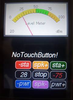
pentru tiparirea grupului de taste si a VU-metrului cu ac. tft.fillScreen(TFT_BLACK); drawCustomKeypad(); analogMeter(); // Draw analogue meter updateTime = millis(); // Next update time digitalWrite(TEST_LED, HIGH); } 7 – In continuare se afla rutina “void loop()”
care ruleaza in bucla pentru gestionarea relatiei dintre placa ESP32, display si alte periferice. ///****************************** LOOP
*******************************/// void loop() { Acesta este codul care va tipari pe Display nivelul
semnalului receptionat (RSSI) in dBm. Culoarea textului se schimba odata cu pragul conventional de
nivel, in Rosu, Alb si Verde, ceea ce reprezinta: Semnal slab, Semnal bun si Semnal foarte
bun. // Print the received signal strength: long rssi = WiFi.RSSI(); Serial.print("RSSI:"); Serial.println(rssi); int16_t currentRSSI = WiFi.RSSI(); if (currentRSSI != previousRSSI) { if (rssi >= -50) {tft.setTextColor(TFT_GREEN);} else if (rssi >= -70 && rssi < -50) {tft.setTextColor(TFT_WHITE);} else {tft.setTextColor(TFT_RED);} if (rssi = 0) { tft.fillRect(185, 255, 40, 20, TFT_BLACK); tft.setTextColor(TFT_RED); tft.setCursor(198, 273); tft.print("0"); } tft.fillRect(185, 255, 40, 20, TFT_BLACK); tft.setCursor(185, 273); tft.print(WiFi.RSSI()); // Display the signal value of the
correspondent previousRSSI = currentRSSI; } //******************************// Urmeaza codul necesar baleajului permanent pentru acul
indicator al Level Metrului. Intr-o aplicatie reala, acest cod trebuie adaptat nevoilor fiecaruia
dintre dumneavoastra. O aplicatie viitoare va incerca constructia unui Walkie
Talkie cu programare si S-metru, imitand o combinatie retro intre o statii
radio Half Duplex si un telefon mobil. if (updateTime <= millis()) { updateTime = millis() + LOOP_PERIOD; d += 4; if (d >= 360) d = 0; //value[0] = map(analogRead(A0), 0, 1023, 0, 100); //
Test with value form Analogue 0 // Create a Sine wave for testing value[0] = 50 + 50 * sin((d + 0) * 0.0174532925); value[1] = 50 + 50 * sin((d + 60) * 0.0174532925); value[2] = 50 + 50 * sin((d + 120) * 0.0174532925); value[3] = 50 + 50 * sin((d + 180) * 0.0174532925); value[4] = 50 + 50 * sin((d + 240) * 0.0174532925); value[5] = 50 + 50 * sin((d + 300) * 0.0174532925); //unsigned long t = millis(); plotNeedle(value[0], 0); //Serial.println(millis()-t); // Print time taken for
meter update } //******************************// Aceasta este cea mai delicata portiune a rutinei “loop”,
intrucat in interiorul ei se asigura verificarea apasatii Touch Screen-ului si
precizia coordonatelor Butoanelor desenate. Contine trimiteri doar catre rutinele de modificare a
puterii de emisie, insa folosind aceste exemple se pot atribui functii
suplimentare Butoanelor ramase libere. Folosirea driverului TFT_eSPI.h este cea mai inspirata alegere pentru controlul
Touch Screen-ului intrucat comparat cu driverul de la Adafruit, acesta are un filtru mai puternic impotriva
erorilor. // Testing the Touch Screen uint16_t t_x = 0, t_y = 0; // To store the touch
coordinates // Pressed will be set true is there is a valid touch on
the screen bool pressed = tft.getTouch(&t_x, &t_y); // Check if any key coordinate boxes contain the touch
coordinates for (uint8_t b = 0; b < 9; b++) { if (pressed && key[b].contains(t_x, t_y)) {key[b].press(true);} // Tell the button it is pressed else {key[b].press(false);} // Tell the button it is NOT
pressed } // Add a check to execute the appropriate functions for (uint8_t b = 0; b < 9; b++) { if (key[b].justPressed()) { if (b == 6) // RED Key { tft.fillRect(0, 175, 240, 35, TFT_BLACK); tft.setTextColor(TFT_BLUE); tft.setCursor(30, 200); tft.print("TouchDownButton!"); TouchDownButton(); } else if (b == 8) // NAVY Key { tft.fillRect(0, 175, 240, 35, TFT_BLACK); tft.setTextColor(TFT_NAVY); tft.setCursor(30, 200); tft.print("TouchUpButton!"); TouchUpButton(); } // The routine can continue with Buttons: 0, 1, 2, 4 and 7 } else if (key[b].justReleased()) { tft.fillRect(0, 175, 240, 35, TFT_BLACK); tft.setTextColor(TFT_WHITE); tft.setCursor(30, 200); tft.print("NoTouchButton!"); } } } 8 – Rutinele folosite sunt bine structurate,
delimitate si au urmatoarele denumiri si functii: - void drawCustomKeypad() * Deseneaza toate Butoanele in
functie de coordonatele centrului butonului “stop”. Aceasta abordare face posibila
mutarea pe display a intregii tastaturi, modificand doar
coordonatele acestuia. // Keypad start position, key sizes and spacing #define KEY_X
75 // Center of key W #define KEY_Y
230 // Center of key Y * Afiseaza puterea WiFi stabilita
din tastatura sau setata pe maxim la pornire. - void Connect_to_WiFi() * Repeta incercarea de conectare la
retea, in serii de cste 10 sec. pana cand este realizata. * Afiseaza pentru cateva secunde
IP-ul local, IP-ul routerului de retea si IP-un P2P. - void TouchDownButton() si void TouchUpButton() * Asigura grafica corespunzatoare
apasarii fiecarui buton si face trimitere catre executia functiilor
stabilite prin program. - void writePower() * Modifica Puterea WiFi pentru
fiecare apasare a butoanelor “–pwr” si “pwr+”. - void analogMeter() si void plotNeedle(int
value, byte ms_delay) * Doua rutine care se ocupa cu
grafica VU-metrului, S-metrului, Level Metrului sau cum doriti dumneavoastra sa-l denumiti.
Rutinele sunt usor de modificat pentru a acoperi o varietate
mare de instrumente. Acul indicator are o miscare identica cu cea a unui instrument
real. Grafica este una dintre cele mai simple si reusite de pana acum. Obsevatii finale: Viteza de rulare a programului poate fi marita semnificativ
prin comentarea cu doua linii oblice a tuturor instructiunilor din seria “Serial.print();”,
folosite in special pentru debug. Compilarea softului se face prin activarea icoanei al Arduino IDE. Incarcarea fisierului rezultat in
mikrocontrollerul ESP32 se face prin conexiunea USB dupa ce portul de
comunicatie a fost setat corespunzator pe ruta Tools > Port: “Com…”. La aparitia mesajului: -
Este foarte important sa se faca o calibrare corecta pentru ca suprafata
Butoanelor sa fie identificata cu precizie de Touch Screen. -
Modificarea puterii de emisie WiFi se face prin tastarea “-pwr”
si “pwr+”. -
In partea superioara a tastaturii este afisata starea Butoanelor intr-un
mod sugestiv si explicit. -
Forma, culorile si schimbarile de stare sunt atribute care fac aplicatia
placuta ochiului, ceea ce vine in completarea functionalitatii acestora. Oricand cei interesati pot modifica, adapta sau dezvolta
aplicatia de fata printr-o gestionare controlata a codului prezentat.
Informatii deosebite puteti obtine si de la Inteligenta
Artificiala prin Chat GPT : https://chat.openai.com/. Pentru
cei ce vor incerca, fac precizarea ca intrebarile se vor pune punctual. Sprijinul meu poate consta in rezolvarea micilor icidente
aparute pe parcursul incercarilor dumneavoastra sau prin oferta de explicatii
suplimentare, atat cat imi permite experienta. Asistenta se poate face la tel. 0742997202
sau prin e-mail: gocomraex@gmail.com Best regards & 73!
Articol aparut la 15-12-2023 2474 Inapoi la inceputul articolului | |
 se apasarea timp
de 3 - 5 sec. butonul Boot. pentru validarea incarcarii in
memoria flash. Rezultatul este prezentat in urmatoarele doua fotografii:
se apasarea timp
de 3 - 5 sec. butonul Boot. pentru validarea incarcarii in
memoria flash. Rezultatul este prezentat in urmatoarele doua fotografii: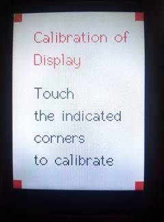
|
Comentariul trebuie sa se refere la continutul articolului. Mesajele anonime, cele scrise sub falsa identitate, precum si cele care contin (fara a se limita la) atac la persoana, injurii, jigniri, expresii obscene vor fi sterse iar dupa caz se va ridica dreptul de a posta comentarii.
| |||||
Opiniile exprimate în articole pe acest site aparţin autorilor şi nu reflectă neapărat punctul de vedere al redacţiei.
|
Copyright © Radioamator.ro. Toate drepturile rezervate. All rights reserved
Articole | Concursuri | Mica Publicitate | Forum YO | Pagini YO | Call Book | Diverse | Regulamentul portalului | Contact |
![]()